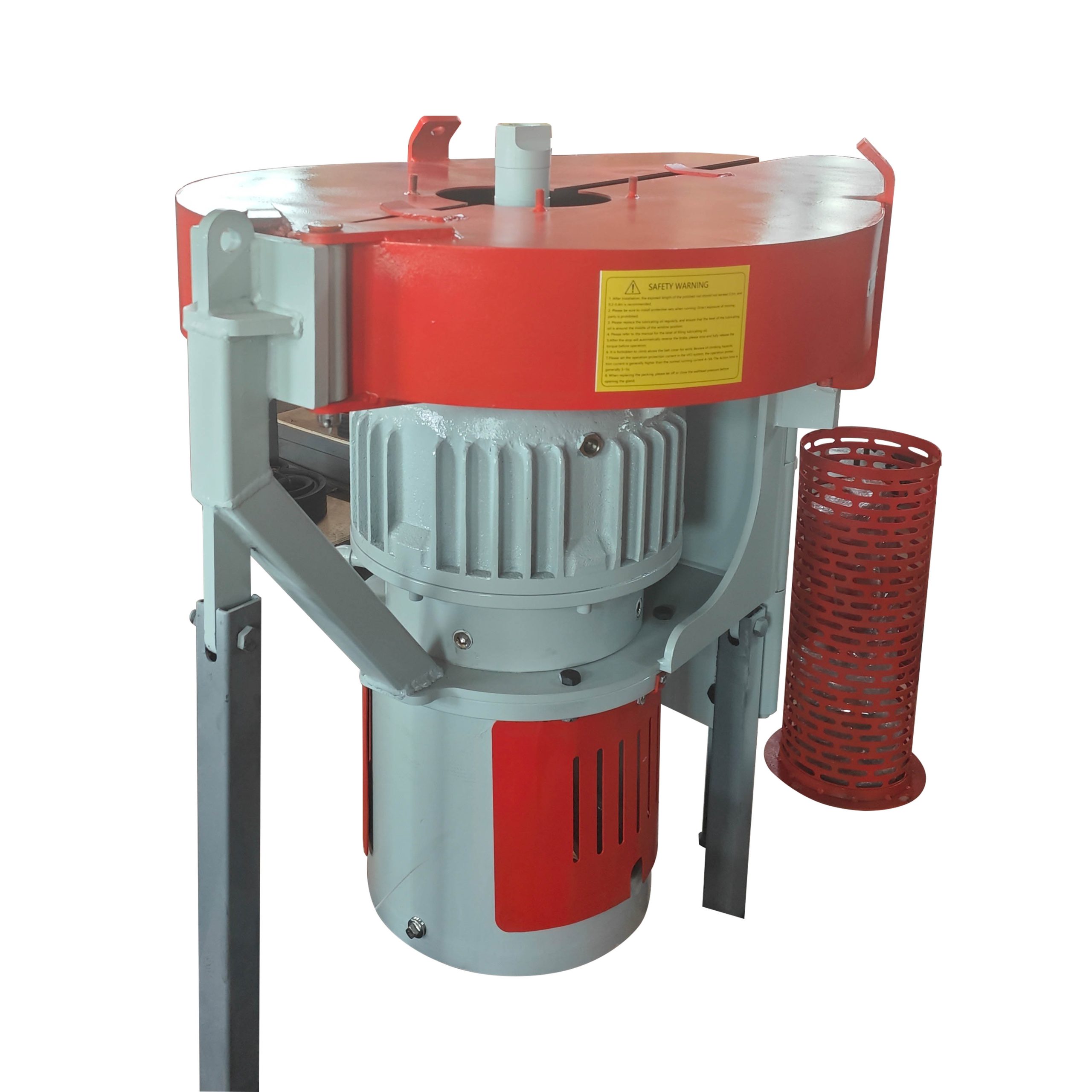
Brief Introduction
Surface Drive and PC pump (Progressive Cavity Pump) is a new type of artificial lift system, which finds more and more applications in the oil fields. Surface drive suspends and rotates rod string and power is then transmitted downhole, which in turn drives the PC pump.
PC pump consists of two parts: rotor and stator. The high strength, chrome-plated rotor is the only moving part of the PC pump. The stator is a kind of tube with elastic synthetic rubber molded inside. A variety of elastomer is available for different applications. When rotor rotates in the stator, a series of sealed cavities are formed and these cavities move axially from the intake end to the displacement side. When one cavity disappears at the displacement side, a new cavity will form at the intake side. Trough continuous formation, motion and disappear of these cavities, fluid is then brought to the surface. Owing to their unique features, the surface drive and PC pump find wide applications in the oil fields, and they are strongly recommended for high viscous, sandy, gassy and water bearing oil.
Schematic drawing of surface drive and PC pump is shown in fig 1.
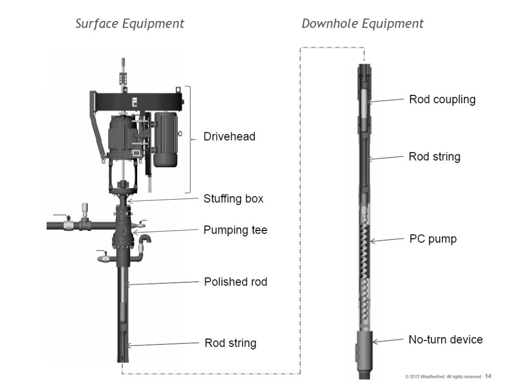
Fig.1 Surface Drive and PC Pump
Major Parts
Surface Drive
The surface drive is a specific facility to suspend and rotate the sucker rod, which in turn drives the PC pump. Then fluid can be brought to the surface by the continuous movement of rotor within stator. When the unit is stop, the surface drive head absorbs reversion torque and prevents thread off. It is mainly comprised of parts showing in fig 2.
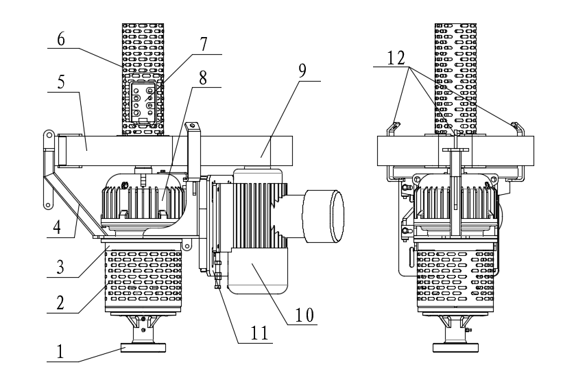

Fig. 2 Surface Drivehead(Single Motor)
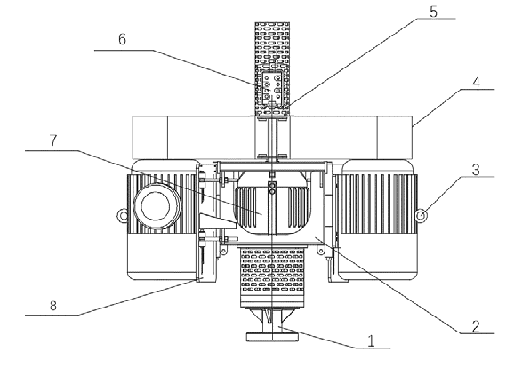

Fig. 3 Surface Drivehead(Dual Motor)
Motor
A Y serial three-phase asynchronous motor is screwed tight on the motor skid and by changing the location of the motor, V-belt tightness can be adjusted effectively. Technical specifications are shown in table 1.
Primary Specification
| Model | Rted Power | Rated Voltage |
Rated Current |
Rated frequency |
Output Speed |
|
|---|---|---|---|---|---|---|
| (kW) | (HP) | (V) | (A) | (Hz) | (r/min) | |
| 1000r/min 6P | ||||||
| YB-160M1-6 | 5.5 | 7.5 | 380/660 | 12.6/7.2 | 50 | 970 |
| YB-160M2-6 | 7.5 | 10 | 380/660 | 16.8/9.7 | 50 | 970 |
| YB-160L-6 | 11 | 15 | 380/660 | 24.3/14 | 50 | 970 |
| YB-180M-6 | 15 | 20 | 380/660 | 31.6/18.3 | 50 | 980 |
| YB-200L1-6 | 18.5 | 25 | 380/660 | 37.6/21.7 | 50 | 980 |
| YB-200L2-6 | 22 | 30 | 380/660 | 44.7/25.8 | 50 | 980 |
| YB-225M-6 | 30 | 40 | 380/660 | 57.6/33.3 | 50 | 980 |
| YB-250M-6 | 37 | 50 | 380/660 | 69.8/40.3 | 50 | 980 |
| YB-280S-6 | 45 | 60 | 380/660 | 85.9/49.6 | 50 | 990 |
| YB-280M-6 | 55 | 75 | 380/660 | 104.7/60.5 | 50 | 990 |
| YB-315S-6 | 75 | 100 | 380/660 | 141.7/81.6 | 50 | 990 |
| 750r/min 8P | ||||||
| YB-160L-8 | 5.5 | 7.5 | 380/660 | 13.4/7.8 | 50 | 720 |
| YB-180M-8 | 7.5 | 10 | 380/660 | 17.5/10.1 | 50 | 720 |
| YB-180L-8 | 11 | 15 | 380/660 | 25.3/14.6 | 50 | 730 |
| YB-200L-8 | 15 | 20 | 380/660 | 33.7/19.5 | 50 | 730 |
| YB-225S-8 | 18.5 | 25 | 380/660 | 40/23.1 | 50 | 740 |
| YB-225M-8 | 22 | 30 | 380/660 | 47.4/27.3 | 50 | 740 |
| YB-250M-8 | 30 | 40 | 380/660 | 63.4/36.6 | 50 | 740 |
| YB-280S-8 | 37 | 50 | 380/660 | 77.8/44.9 | 50 | 740 |
| YB-280M-8 | 45 | 60 | 380/660 | 94.1/54.3 | 50 | 740 |
| YB-315S-8 | 55 | 75 | 380/660 | 111.2/64 | 50 | 740 |
Explosion-proof motor, VF motor, VF Explosion-proof motor can also be provided. Protection grade is rated as IP55 for the conventional motor and explosion proof grade as dⅡBT4 motor shows wide speed adjust range from 0 to 100Hz.
Main technical parameters of commonly used NEMA series motors
| Model | Rted Power | Rated Voltage | Rated Current | Rated frequency | Output Speed | |
|---|---|---|---|---|---|---|
| (kW) | (HP) | (V) | (A) | (Hz) | (r/min) | |
| 1200r/min 6P | ||||||
| 254T-6 | 5.5 | 7.5 | 440/480 | 10.4 | 60 | 1170 |
| 256T-6 | 7.5 | 10 | 440/480 | 13.6 | 60 | 1170 |
| 284T-6 | 11 | 15 | 440/480 | 19.2 | 60 | 1170 |
| 286T-6 | 15 | 20 | 440/480 | 25.6 | 60 | 1170 |
| 324T-6 | 18.5 | 25 | 440/480 | 30.9 | 60 | 1170 |
| 326T-6 | 22 | 30 | 440/480 | 36.3 | 60 | 1170 |
| 364T-6 | 30 | 40 | 440/480 | 48.5 | 60 | 1180 |
| 365T-6 | 37 | 50 | 440/480 | 61.5 | 60 | 1180 |
| 404T-6 | 45 | 60 | 440/480 | 71.6 | 60 | 1180 |
| 405T-6 | 55 | 75 | 440/480 | 87.5 | 60 | 1185 |
| 444T-6 | 75 | 100 | 440/480 | 119.4 | 60 | 1185 |
Generally, the countries that implement NEMA motor standards are mainly North America, South America and other regions, and the commonly used matched motor access power is generally 3 ~, 60Hz, 440 ~ 480V and so on. According to the custom of NEMA motor, different explosion-proof grades and NEMA series protection grades are matched.
series surface drive specification:
| Model | Polished rod specification | Max. output torque | Bearing axial load | Size | Notes |
|---|---|---|---|---|---|
| RTM1000 | 1 ¼-in. or 1 ½-in. | 1350 N.m | 12 T | 1200×750×1400 | Single motor drive |
| RTM1500 | 1 ¼-in. or 1 ½-in. | 2030 N.m | 18 T | 1330×845×1500 | Single motor drive |
| RTM2000 | 1 ¼-in. or 1 ½-in. | 2700 N.m | 22T | 1540×890×1750 | Single motor drive |
| RTM2000XL | 1 ¼-in. or 1 ½-in. | 2700 N.m | 30T | 1540×890×1750 | Single motor drive |
| RTM2000D | 1 ¼-in. or 1 ½-in. | 5060 N.m | 22 T/30T | 1940×1040×1750 | Dual motor drive |
| RTM3750D | 1 ½-in. | 5060 N.m | 30 T | 1940×1040×1750 | Dual motor drive |
| RTM1500 Belt pulley matching table | ||||||||
|---|---|---|---|---|---|---|---|---|
| Power kW | Speed rpm | Reduction ratio | Small pulley diameter in | Large pulley diameter in | Small pulley shaft sleeve | Large pulley shaft sleeve in |
Pulley type | Groove |
| 18.5 | 970 | 3.9 | 7.1 | 28 | SK48 | E2 3/4 | 5VX1030 | 3 |
| 970 | 4.7 | 5.9 | 28 | SK48 | F2 3/4 | 5VX1000 | 5 | |
| 22 | 970 | 3.9 | 7.1 | 28 | SF55 | E2 3/4 | 5VX1030 | 4 |
| 970 | 4.7 | 5.9 | 28 | SK55 | F2 3/4 | 5VX1030 | 6 | |
| 30 | 980 | 3.1 | 8 | 25 | SF60 | E2 3/4 | 5VX1000 | 4 |
| 980 | 3.9 | 7.1 | 28 | SF60 | F2 3/4 | 5VX1060 | 6 | |
| 37 | 980 | 3 | 9.25 | 28 | SF65 | E2 3/4 | 5VX1080 | 4 |
| 980 | 4.2 | 6.7 | 28 | SF65 | J2 3/4 | 5VX1060 | 6 | |
| RTM2000、RTM3750 Belt pulley matching table | ||||||||
|---|---|---|---|---|---|---|---|---|
| Power kW | Speed rpm |
Reduction ratio | Small pulley diameter in |
Large pulley diameter in |
Small pulley shaft sleeve | Large pulley shaft sleeve in |
Pulley type |
Groove |
| 30 | 980 | 4.7 | 6.7 | 31.5 | SF60 | F2 3/4 | 5VX1230 | 5 |
| 1470 | 5 | 6.3 | 31.5 | SK65 | F2 3/4 | 5VX1180 | 4 | |
| 37 | 980 | 4.7 | 6.7 | 31.5 | SF60 | F2 3/4 | 5VX1230 | 6 |
| 1480 | 4.7 | 6.7 | 31.5 | SK65 | F2 3/4 | 5VX1230 | 5 | |
| 45 | 980 | 4.44 | 7.1 | 31.5 | SF65 | F2 3/4 | 5VX1250 | 7 |
| 1480 | 4.7 | 6.7 | 31.5 | SF60 | F2 3/4 | 5VX1230 | 5 | |
| 55 | 980 | 4 | 8 | 31.5 | E75 | J2 3/4 | 5VX1250 | 6 |
| 1480 | 4.7 | 6.7 | 31.5 | SF65 | J2 3/4 | 5VX1250 | 6 | |
| 75 | 980 | 3.94 | 8 | 31.5 | E80 | M2 3/4 | 5VX1250 | 8 |
| 1480 | 3.94 | 8 | 31.5 | E75 | J2 3/4 | 5VX1250 | 6 | |
Detailed technical parameter description:
| Item | VED1000 | VED1500 | VED2000 | VED2000XL | Remark |
|---|---|---|---|---|---|
| Maximum output | |||||
| torque(ftꞏlb/Nꞏm) | 1000/1350 | 1500/2030 | 2000/2700 | 2000/27000 | |
| Maximum output speed(rpm) |
600 | Different speed can be selected |
|||
| Maximum axial load ( Lb/kN) |
30000/150 | 39600/180 | 48500/220 | 66000/30 | |
| Maximum base of motor(IEC/NEMA) | IEC 200L/ NEMA 326T |
IEC 250M/ NEMA 405T | IEC 280M/ NEMA 445T | IEC 280M/ NEMA 445T | |
| Motor installation mode |
Vertical motor shaft up,V5 | |
|||
| Motor protection | IP54/55 | selectable | |||
| Motor explosion-proof | EXDIIBT4 | claimable | |||
| Matching motor speed(rpm)@60Hz/50Hz | 1160/960 | 4P/6P/8P | |||
| Rod specification | 1 ¼-in. or 1 ½-in | 1 ¼-in. or 1 ½-in or larger |
customizable | ||
| Power type | Motor 0r internal combustion engine | default motor | |||
| Power | 3~,50Hz,380V Or 3~,60Hz,460V | customizable | |||
| Spindle type | hollow spindle | |
|||
| Spindle diameter | 2-3/4”(Φ70) | |
|||
| Driving belt pulley specifications (in/mm) |
6in(150)/7in(180)/8in(200)/9-5/8(244) | claimable | |||
| Driven pulley specification(in/mm) |
22in(560)/24.8in(630)/28in (710)/31.5(800) | claimable | |||
| Maximum deceleration ratio |
5.1 | |
|||
| Break method | Wet centrifugal brake | ||||
| Box heat dissipation | Ribbed radiator | ||||
| Connection mode between rod and drive shaft |
6 screw or 8 screw rod clamp | |
|||
| Rod sealing | Stuffing | ||||
| Stuffing material | PTEE / Graphite carbon fiber | ||||
| Stuffing box Bottom connection |
73/89EU pin,3-1/8 3000PSI,2-9/16 3000PSI | customizable | |||
| Rod sealing BOP | Optional single or double ram, take out port, etc., to adapt to the smooth rod specifications |
customizable | |||
| Environmental conditions |
Outdoor, no more than 4500m above sea level, temperature -45~+50℃ |
|
|||
Wet centrifugal brake system
Braking System:The action of the backspin brake will result in controlled recoil speed until the energy is completely released.
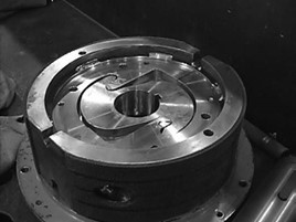
The braking system utilizes a patented totally enclosed backspin control system that will automatically work whenever the normal forward rotational speed is interrupted and forces the system to rotate backwards.
The braking system uses centrifugal force during backspin to engage the large shoes against a stationary housing.
The braking system is immersed in synthetic oil that controls fluctuating temperatures while lubricating all the internal moving parts.
Stuffing Box
Stuffing box on the drive head is designed for the purpose of preventing oil leak occurred at the polished rod. By pressing packing in the stuffing box, oil leak can be eliminated. Owing to the two-stage sealing feature of the stuffing box, packing can be changed even when the wellhead still bears downhole pressure.
By pressing the packings tight against the polished rod, oil leakage can be prevented from the packing box. The packing box has a secondary sealing device, which makes packing change possible under well pressure. Various types of stuffing boxes are designed for different solutions, such as threaded stuffing box, clamped stuffing box, wellhead type stuffing box and rubber valve type stuffing box. The wellhead type stuffing box can directly connect the lower part of the surface drive to wellhead. The whole unit becomes more stable in unit structure and system running due to its lowered gravity center. Flow tees are available if necessary.
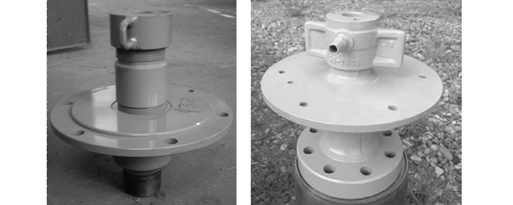
Fig 9 Stuffing Box Types
| Type | Connection Type | Packings | Remarks |
|---|---|---|---|
| Flange | API 3-1/8,2-9/16,3000PSI | PTFE、Kevlar、 Graphite fiber | Connection flange can be made to requirements. |
| Threaded | 2 7/8 or 3 1/2 EUE or NUE | To be threaded according to requirements | |
Notes: All stuffing boxes are applicable for polished rod in φ38、φ36、φ34、φ32、φ28(notice: conversion to British unit)diameters, but after selecting the stuffing box, polished rod size need to be stated as well in the order.
Features:
- Packing seal is adopted to withstand large pressure, showing reliability and safe performance;
- The sealing type is similar to heavy oil stuffing box, making maintenance easy and convenient;
- Various types of connections are available for different types BOP and wellheads;
- The secondary sealing feature of the stuffing box makes packing change possible under well pressure. No need to drain pipelines. Well site contamination caused by oil leakage can be avoided.
Packing Change Steps:
Usually, the packings do not need to be changed, even if mild leakage occurs. Screw tight the press cap downward with tool until no leakage is found at the stuffing box. If the press cap can not be screwed down, then packing change is needed.

Fig 10 Stuffing Box
- Stop the unit according to requirements, with all necessary tools ready;
- When the wellhead completely stops, close tight the master valve and open the sampling valve to drain tubing pressure;
- When tubing pressure is zero, loose the press cap. Take out the burnt packings with specialty tools, replace new packings and screw tight press cap again.
- Close the sampling valve and open the master valve. Start up the unit according to requirements.
Note:Make sure wellhead pressure is ZERO when changing the packings. This can be done by drain pressure trapped in the pipelines, screw tight the secondary seal or the tie-down bolts of rubber vale.
Electric Panel
The electric panel controls and protects normal operation of the unit. General electric panel and variable speed control panel are available for use.
Drive unit operation control system:
The main function of the control cabinet is PCP well driving and control, taking into account the display and control of oil well pressure, temperature, casing pressure, dynamic fluid level and other technical parameters, with the control system to form closed-loop control, automatic adjustment, can be set according to different well conditions; At the same time, it can form PID automatic adjustment control with the level of downhole dynamic fluid level, or other control methods (such as timing production, fixed displacement production, fixed speed production, etc.). This series of control cabinet has outdoor use requirements, IP54 protection level, adopts double door design, perfect sealing function, adapt to the local all-weather outdoor use conditions in Indonesia.
Main technical description:
| Items | Technical parameters | Notes |
|---|---|---|
| Control cabinet name | PCP integrated control cabinet | |
| Control cabinet model | LBK-ZN | Adaptive Power Control 75kW(100HP) |
| Rated voltage | 3~,460V,60Hz/3~,50Hz,380V | According to the use area of the industrial three-phase matching |
| Adapt to the voltage range | 380~480V(-10~+15)% | Wide voltage for use |
| Frequency range | 50/60Hz | |
| Rated Current | According to the matching motor power | |
| Motor power | According to the matching motor power | |
| Adjust frequency range | 5~100Hz/5~120Hz | Matching variable frequency motor |
| Inverter brand | ABB Or other brands | Global joint venture brand |
| Frequency converter model | ABB580 Or other series | Rated current 046A,Voltage 380~480V,50/60Hz |
| Installation mode of the frequency converter | wall mounting type | |
| Frequency converter language | Chinese / English /Russian | Can be selected on the control panel, can restart the frequency conversion |
| Control disk type | Assistant type | |
| Control disk display | Output current, voltage, frequency, operating speed and other parameters | The display interface can be adjusted manually |
| Frequency adjustment mode | Potentiometer knob adjustment | Can also switch to the frequency converter button adjustment or preset frequency |
| Touch screen setting | The operating frequency can be set directly through the software | |
| Touch screen size | 7in/10in | Resistance screen, according to power or customer requirements |
| Accessible sensor | Oil pressure, casing pressure, oil temperature and other parameters | (On-site sensor provided by customer) |
| Type of accessible signal | 4~20mA,RS485Communication, etc., switching signals, etc | Communicate the communication protocol and function in advance, and can be preset |
| Cabinet display instrument | Amperemeter | Measure the incoming line current |
| Voltmeter | Measure the incoming voltage | |
| Frequency changer | Assistant display panel | |
| Touch screen | Display system running state (including running electrical parameters, electric quantity, output torque,running speed and other parameters) and system | |
| |
Settings, etc. Display well oil pressure, casing pressure, temperature, hydrodynamic level, etc. (relevant sensors or test instruments are required and closed loop automatic control is formed with the control cabinet system | |
| Protection function | Overcurrent, overvoltage,and overload protection | |
| Missing phase, under voltage, underload protection | ||
| Short circuit, blocking and other functions | ||
| Emergency-stop protection function | Red emergency stop button on the outer side of the cabinet | |
| An incoming call is a self-starter | No fault power failure and then the electric delay from the start | can set interval between incoming calls |
| Wind and sand prevention function | Fully closed cabinet, cable entry with cable faset sealing, cabinet on both sides of the sand filter cotton, to ensure the clean entry air | |
| Rain prevention function | Cabinet top rain hat design, the cabinet body has rain tank, rubber, sealing strip sealing and other functions | |
| Automatic dehumidification function | Suitable for high humidity weather in Indonesia, automatic dehumidification before starting or running | Optional, according to regional characteristics to choose |
| Automatic heating function | -5℃ Adjustable | Mechanical temperature induction regulator, manual adjustment, when the cabinet temperature exceeds the temperature will automatically dissipate heat |
| Heat dissipation temperature of the fan in the cabinet | 35℃ | Mechanical temperature induction regulator, can be manually adjusted, when the temperature in the cabinet exceeds this temperature will automatically heat |
| Number of cooling fans | 2 or more | According to power and cabinet size |
| Terminal inside the cabinet | Main incoming line wiring terminal | Connect the power supply to the control cabinet |
| Main outgoing line wiring terminal | Connect the frequency conversion cabinet and PCP motor power cable | |
| Terminal of the frequency conversion fan appears | Connecting the motor tail heat fan | |
| Sensor terminal | Reserve three to four 4 to 20mA signal terminals | |
| Pressure switch terminal | Overpressure alarm, switch quantity (pipeline pressure switch) Normally open and normally closed can be switched | |
| Temporary terminal | Temporary electrical | 3~,380V,220V |
| terminal | ||
| Cabinet design features | Double door design, front and back can be opened | The rear door is convenient for follow-up maintenance; The outer door is for outdoor use, and the inner door is for button and instrument control panel; Temporary electric separate side open the cabinet door |
| The inner door panel is inlaid with operation buttons | ||
| Air circulation mode | Side ateral in and out | |
| Support of cabinet installation method | Split assembly | The underground embedding depth is 600-800m, and the ground height is 400mm. For Angle iron welding disassembly split, can be assembled on site |
| Overall dimensions of the cabinet body | 800*600*1530/other size | Estimated size, not including cabinet leg size |
| Overall weight of the control cabinet | 250kg | Expected weight |
| levels of protection | IP54 | |
| Where to use | Outdoor / indoor | |
| Adapt to the ambient temperature | -45~+45℃ | |
Drivehead-Vertical motor Install
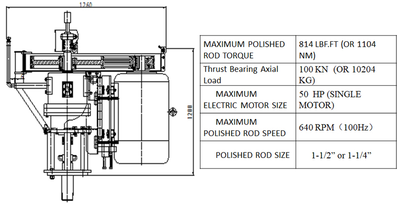
| Model | LBQ-25 |
|---|---|
| Sheave Model | SPB-4 |
| Sheave Ratio | (Big Sheave)φ710mm/φ236mm (Small Sheave) |
| Sheave Ratio | 0~640rpm (0~100Hz)The speed can be adjusted by changing the size of the belt sheave |
| Motor Power | 25HP(18.5kW)Provided by the customer |
| Max. Matching Power | 50HP(37kW) |
| Axial Load | 100 KN |
| Polished Rod | 1-1/4”;1-1/2” etc. |
| Wellhead Connection | API 6B 3-1/8” 3000PSI |
| Brake System | Built-in Centrifugal Brake System |
| Weight | 580kg |
| Torque | As per motor power(sheave reducer ratio 3) (At 50 HP, 50HZ, the corresponding rated torque: 1104 Nm) |
PCP Drivehead-(MG seriers)
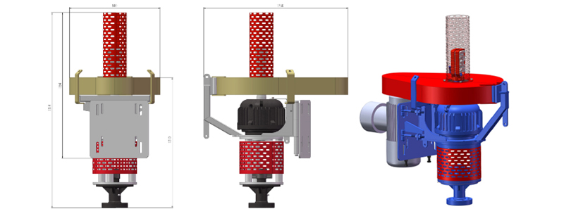
PCP Drivehead -Double motor series
•Dual motor Drive Head
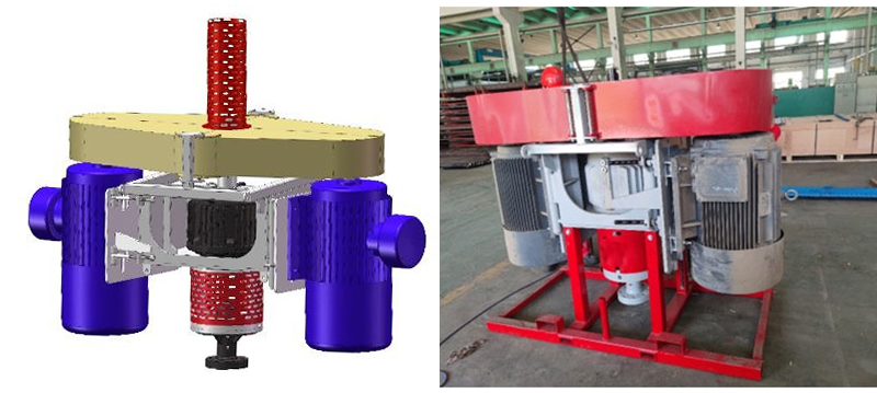
Generally, it is matched with super-large power (75HP*2,100HP*2) driving device, which is applied in South America (Venezuela, Peru) and so on to drive deep well large-displacement screw pump. The driving device is a wet centrifugal brake system.
PCP Drivehead- Centrifugal brake
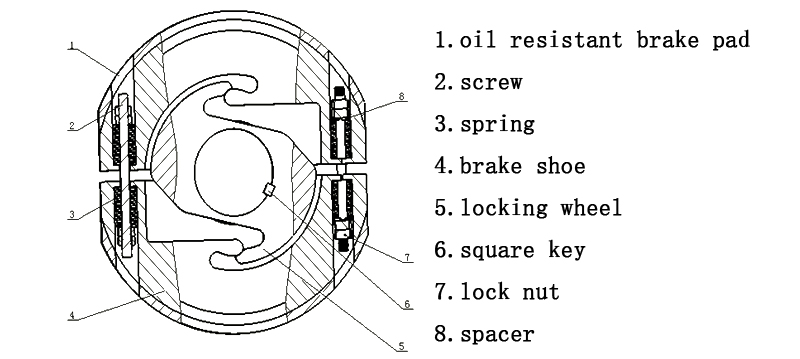
When reversing(negative rotation), the lock wheel 5 is detached from the brake shoe 4 and separated. The lock wheel 5 reverses with the main shaft and drive the brake shoe 4 turns. The brake shoe 4 reversal generates centrifugal force and along the screw 2 axial expansion, oil resistant pad 1 at this time in contact with the housing inner wall, thus producing brake force, the faster the reverse speed, the bigger the centrifugal force, the greater the brake braking force.
| Model | Polished rod specification | Max. output torque | Bearing axial load | Size | Notes |
|---|---|---|---|---|---|
| VED1000 | 1 ¼-in. or 1 ½-in. | 1350 N.m | 12T | 1200×750×1400 | Single motor drive |
| VED1500 | 1 ¼-in. or 1 ½-in. | 2030 N.m | 18T | 1330×845×1500 | Single motor drive |
| VED2000 | 1 ¼-in. or 1 ½-in. | 2700 N.m | 22T | 1540×890×1750 | Single motor drive |
| VED2000XL | 1 ¼-in. or 1 ½-in. | 2700 N.m | 30T | 1540×890×1750 | Single motor drive |
| VED2000D | 1 ¼-in. or 1 ½-in. | 5060 N.m | 22T/30T | 1940×1040×1750 | Dual motor drive |
| VED3750D | 1 ½-in. | 5060 N.m | 30T | 1940×1040×1750 | Dual motor drive |
PCP Drivehead- Permanent magnet direct drive motor
- Low noise (test noise around 60dB (A)), simple structure and easy maintenance;
- Low energy consumption, high efficiency and low temperature rise;
- 0-500rpm stepless variable speed, fully electrical control.
- Adopt no-oil seal design, no lubricating oil leakage, etc.
- High torque, high overload capacity, can withstand 2 times of torque short time overload.
- Soft start: through frequency conversion control, the speed of the system starts slowly and smoothly, so as to avoid the damage of the rod column of the screw pump by impact force and extend the service life.
- Soft brake: with advanced and reliable built-in brake unit and brake resistance, the brake force can be adjusted automatically according to the reverse speed, and the elastic potential energy of the pump can be gradually released.
| Model | Power (kW) |
Speed Range (rpm) |
Voltage (V) |
Torque (N·m) |
Starting Torque (N·m) |
|---|---|---|---|---|---|
| LZQ280-11-700 | 11 | 0~500 | 380 | 700 | 2100 |
| LZQ280-15-850 | 15 | 0~500 | 380 | 853 | 2559 |
| LZQ280-18-1100 | 18 | 0~500 | 380 | 1101 | 3303 |
| LZQ280-22-1350 | 22 | 0~500 | 380 | 1350 | 4050 |
| LZQ315-30-1900 | 30 | 0~500 | 380 | 1910 | 5730 |
| LZQ315-37-2350 | 37 | 0~500 | 380 | 2355 | 7065 |
| LZQ315-45-2860 | 45 | 0~500 | 380 | 2865 | 8595 |

